Terra – The Sustainability Pavilion
Terra – The Sustainability Pavilion opened to the public in October 2021 as one of the top three attractions of the Expo 2020 Dubai. Designed by Grimshaw architects, the sustainability drivers for the pavilion were net zero energy and water.
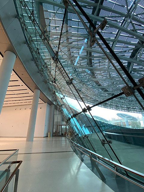
In Dubai’s harsh environment where summer temperatures can reach 50 deg C, shading was provided by a 130m wide main roof canopy and below-ground accommodation. More than 6,000 sqm of monocrystalline photovoltaic cells are embedded in the canopy’s glass panels. These cells and the glass casing allow the pavilion to harness solar energy while providing shade and daylighting to the occupants. At the centre of the pavilion a courtyard provides a passively cooled space for visitors by using the prevailing cool breezes and blocking harsh winds.
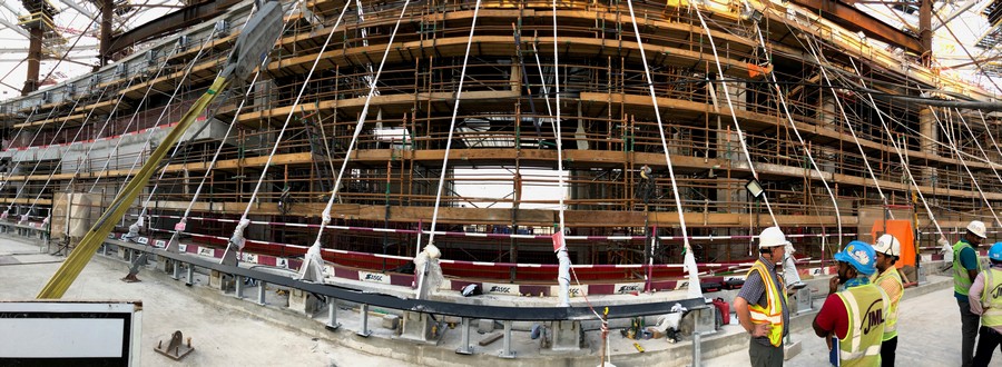
Inhabit was appointed by façade contractor JML in September 2017 to carry out the structural design and engineering of all cable façades systems including the IGU glass and custom patch fittings. The Dubai team also provided construction support throughout to the main contractor, ASGC Group, and parametric design of the solar panel canopy for Premier Composite Technologies (PCT). The project was completed at the end of 2019.
“The scope included the main internal courtyard and lobby entrances where the cable façade spanned over glazed vestibules. Inhabit was later appointed to design and engineer the jacking system for tensioning the cables, and site supervision during installation and testing. Our client was very happy with the outcome of the cable façade system and especially impressed with the innovative engineering design that helped deliver the project. It was a privilege to be part of such an iconic project with extremely complex engineering problems.”
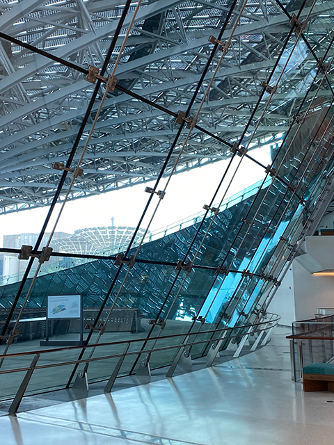
CABLE FAÇADE SYSTEM CASE STUDY
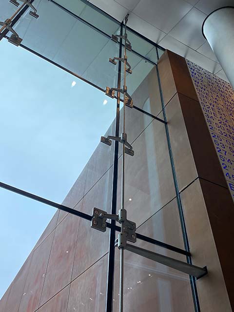
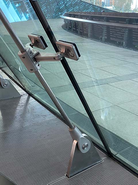
The cable façade system is made up of a pre-tension cable with varying cable diameter depending on the span and location of the cable, the pre-tensioned cable is fixed back to concrete substructure by means of a duplex stainless-steel bracket.
The following requirements had to be considered in the design and engineering process to deliver a system that met our client’s vision;
. Architectural requirements
. Building maintenance requirements
. Building movement and cable differential deflection
. Load case consideration
. Structural analysis of cables
. Staging of jacking process
ARCHITECTURAL
In both elevation and plan the façade is curved, increasing the complexity of design and building movement as the cables were different in length and diameter. The difference in length would cause issues with differential deflections between cables. The architect specified a cable system that was jacket (tensioned) through the base bracket, which significantly increased the difficulty of installation compared to the more typical method of tensioning through a turn buckle system. The architectural intent resulted in a more elegant and ecstatically
pleasing system as the cable is uninterrupted and disappears into the floor and soffit.
BUILDING MAINTENANCE REQUIREMENT
Over time the tension in the cable reduces due to external factors such as building movement, thermal expansion and creep. The client requested no re-tensioning of the system to be done for 25 years. Our analysis allowed for this by considering the amount of building movement, creep and thermal expansion for the specified period. The cables were pre-tensioned during
the manufacturing phase to limit the amount of strain during the in-service life and advised on expected strain values based on historic test data.
Arguably the most important factor to consider is the building movement. Inhabit carried out a comprehensive building movement assessment liaising with the structural engineer to understand exactly how the supporting concrete structure will behave once the large tension loads are applied to the cable. The following information was requested from the structural engineer:
1) Short-term creep
2) Long-term creep
3) Superimposed dead load
4) Superimposed live load
5) Column shortening
This was an iterative process as the amount of building movement was directly related to the cable tensioning and vice versa. The engineers had to consider the differential deflection of the cables due to a difference in cable length and diameter (cable diameter is smaller where spans were smaller). This is a very important aspect as the insulated glass unit was limited in the amount by the amount of warp it could experience.
LOAD CASE CONSIDERATIONS
Typically, one would look at the dead load, wind load, imposed live load, imposed dead load and seismic load when doing the structural analysis for a façade system. The system would be designed in such a way that the expected building movement and thermal expansion is accommodated in the connections so that it does not affect the structural integrity of the façade system. With cable facades the structural analysis must consider the effect of building movement and thermal expansion as it reduces the tension force within the cable and therefore the capacity of the system. For this reason, all load cases also considered building movement and thermal expansion.
STRUCTURAL ANALYSIS OF CABLES
Inhabit carried out a comprehensive structural analysis of the full cable façade using Strand 7 finite element analysis software by means of a non-linear analysis. The software allowed the Inhabit make the following modifications which assisted in the accuracy of the analysis:
1) Modify the cable mechanical properties to match the suppliers test data;
2) Apply a pre-tension load to the model simulating actual loading conditions;
3) Move the top connection point of the cable simulating building movement.
The following output parameters were used to assess and confirm the suitability of the cable diameter and pre-tension setting:
1) Stress output of each cable;
2) Global deflection of each cable;
3) Differential deflection between 2 adjacent cables, to further analyse the warp of each IGU
The structural calculations were prepared in a professional report and submitted to a third-party façade consultant for review and approval before fabrication could commence.
-
ScopeFAÇADE CONSULTING
-
LocationDUBAI, UNITED ARAB EMIRATES
-
ClientJML FAÇADES + ASGC GROUP
-
ArchitectGRIMSHAW